

Bilder vom Tag des offenen Hackerspace
Keiner hackt feiner! Besucht uns am internationalen Tag des offenen Hackerspaces!
Testing replacement fuses for Fluke multimeter from AliExpress
 Dinge von snowball
Bilder vom Tag des offenen Hackerspace
03. 04. 2023
Am 25.3. haben wir unsere Türen für den internationalen Tag des offenen Hackerspaces geöffnet. Wir haben viele Projekte zeigen können, von Linux auf einem bl808 über die Druckluftorgel, unseren Dodekaeder, einen Roboterarm und aktuelle KI-Themen. Neben den Projekten gab es drei Vorträge, an denen sich auch das Publikum aktiv beteiligt hat.
Wir konnten viele interessierte Gäste durch unsere Räume führen. Einige davon haben uns beim Hackerfrystyck erneut besucht. Kommt auch gerne mittwochs zum OpenChaos vorbei.
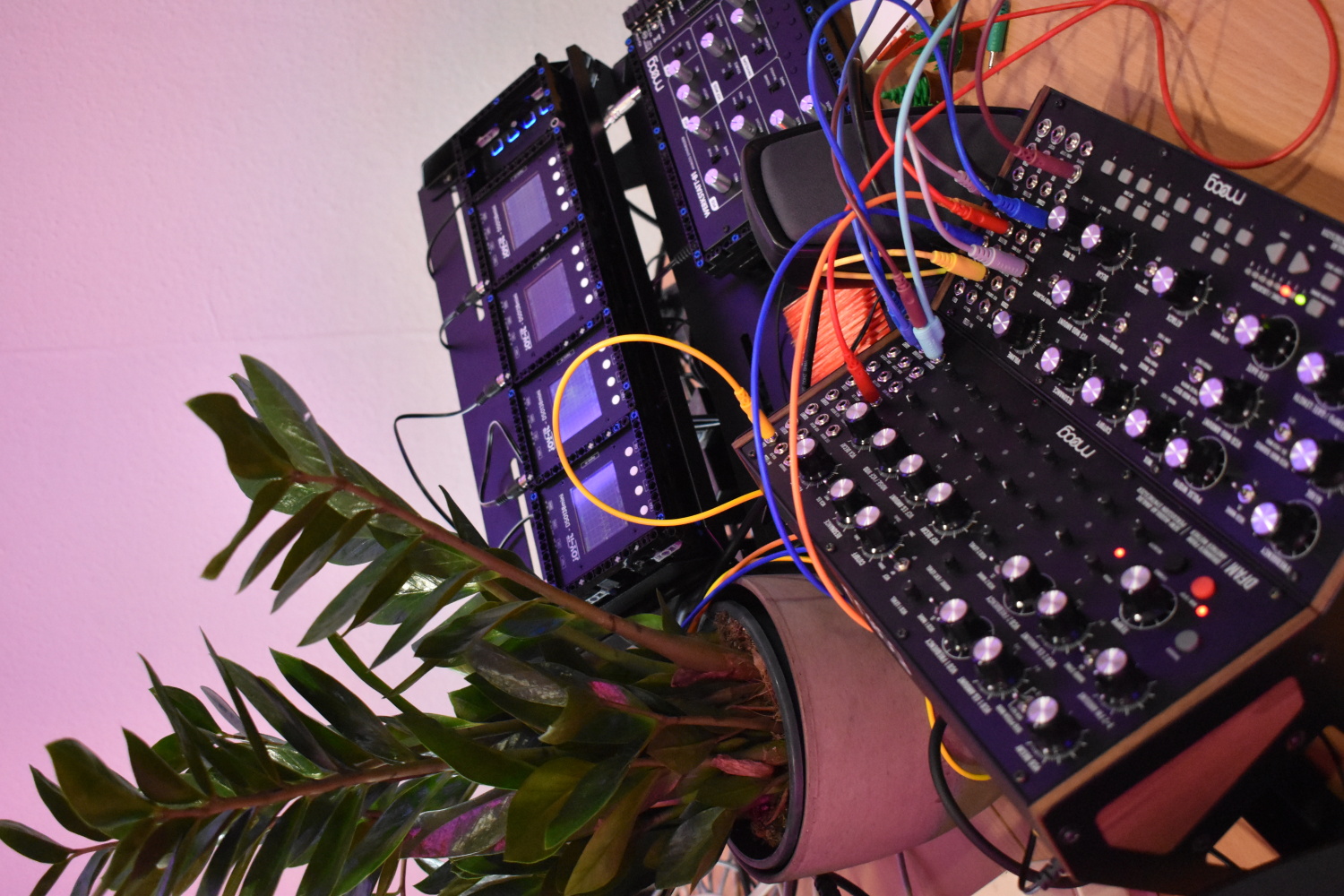
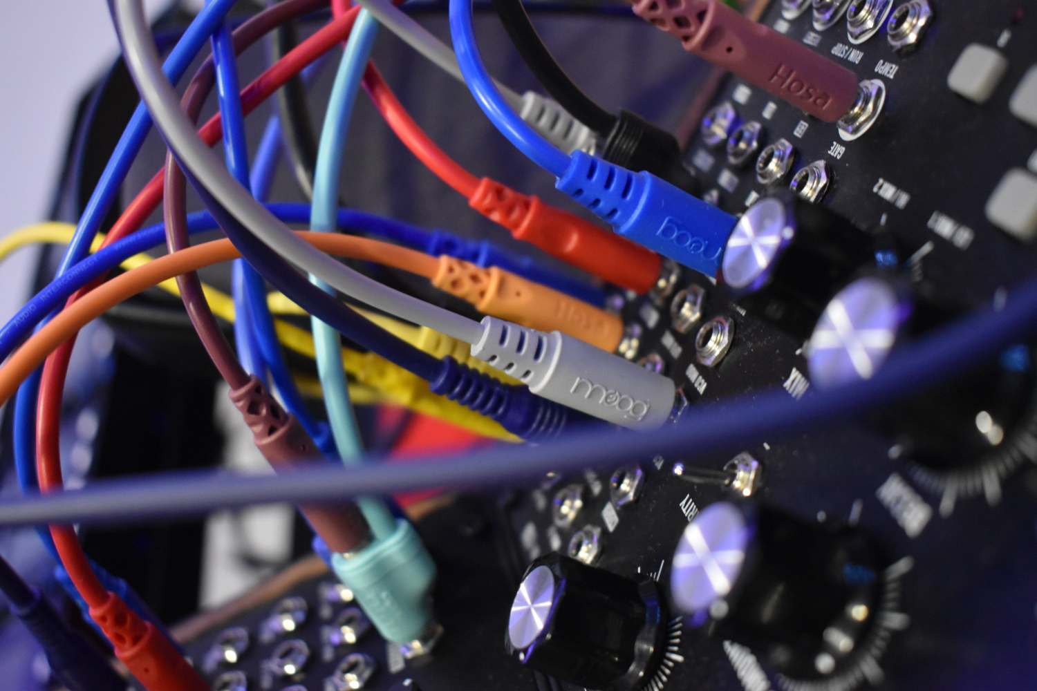
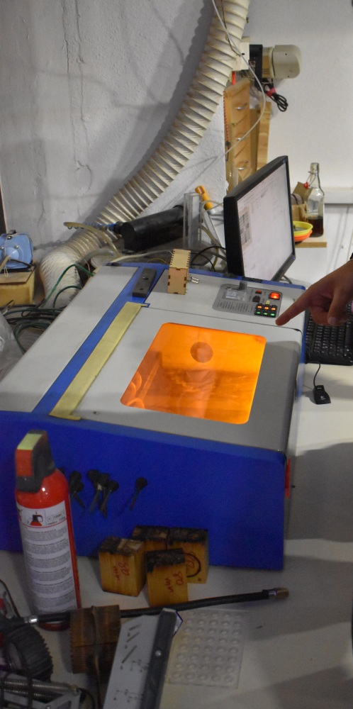
Hier ein paar Eindrück von dem Tag (zugunsten des Datenschutzes ohne Personen oder mit Mitgliedern, die dem zugestimmt haben):
 |
|||||
 |
 |
 |
|||
 |
 |
||||
 |
 |
||||
Keiner hackt feiner! Besucht uns am internationalen Tag des offenen Hackerspaces!
16. 03. 2023
Zum 1010₂-ten Internationalen Tag (und Nacht!) des offenen Hackerspaces öffnen am 25. März über sechzig Hackerspaces wieder die Türen und laden Neugierige und Wissbegierige ein, uns in unseren natürlichen Habitaten zu besuchen.
Auch wir laden dazu in unsere Vereinsräume ein, um mit echten Nerds und Hackerinnen zusammenzukommen und dabei zu sein, wenn wir mit Euch gemeinsam Hardware und Hackingmythen zerlegen. Egal ob du dich für künstliche Intelligenz interessierst oder für Datenschutz und offene Software; ob du lieber mit Holz, Metall und Leder baust statt mit der Tastatur; ob du kreativ bist mit buntem Licht, Schneidplotter oder Textil ‒ bei uns findest du sicher jemanden mit ähnlichen Interessen. Komm auf einen Kaffee vorbei oder bring deinen Laptop mit und lass dich länger nieder. Ein interessantes Projekt findest du bestimmt bei uns!
Als Gesprächsanstoß wird es einige Vorträge geben: „Shamir Secret Sharing“ (Kryptographie), „Versions- und Dateiverwaltung mit git“ und „ChatGPT produktiv nutzen“. Außerdem präsentieren wir einige Projekte, die bei uns oder in der Open Source Community entstanden sind.
Wenn du an dem Tag nicht in Paderborn sein kannst, schau doch mal, ob es auch in deiner Stadt oder deinem Land einen Hackerspace gibt. Auf dieser Karte findest du jeweils Links zu den teilnehmenden Spaces.
Dabei sind die Hackerspaces so divers wie die Städte, in denen sie gewachsen sind, und wie die Leute, die in ihnen heimisch geworden sind ‒ und Ihr könnt der Anstoß für eine ganz eigene Forschungs-, Bastel- oder Philosophie-Nische in Erfas oder Chaostreffs in Eurer Nähe werden. Denn diese Spaces stehen für einen kreativen Umgang mit Technik, sind aber auch Orte, um endlich normale Leute zu treffen.
Kommt zahlreich!
Die wichtigsten Infos im Überblick:
- am Samstag, 25. März 2023, ab 13 Uhr
- Vorträge zwischen 15 und 16 Uhr
- Im Subraum in der Westernmauer 12-16, 33098 Paderborn. Eine Wegbeschreibung mit Foto findest du hier.
- Abweichend von unserer sonstigen Regelung gilt an dem Tag keine Maskenpflicht. Du darfst natürlich gerne eine Maske tragen, wenn du das möchtest. Falls du dicht nicht gut fühlst oder deutliche Krankheitssympthome zeigst, würden wir dich bitten an dem Tag zu Hause zu bleiben und stattdessen z.B. Mittwochs zum Open Chaos vorbei zu kommen.
- Bei Rückfragen kannst du uns unter mail@c3pb.de erreichen.

Testing replacement fuses for Fluke multimeter from AliExpress
23. 05. 2021
I just wanted to double-check the voltage before plugging the power supply connector into my board and then I was confused because it read as zero volts. Of course, I had still plugged the test leads into the current input and of course that killed the fuse. My other multimeter (an older Mastech) complains very loudly when the leads are plugged into the wrong holes but this time I was using the Fluke. Fuses can’t be too expensive, can they? Well, they can. That’s more than 10€ with shipping and other sources aren’t much cheaper.
On Ebay, I saw cheap alternatives with shipping from China and I was curious. I ordered 10 pieces on AliExpress for 15€, which is only slightly more than what I would have paid for one original. I had some previous experience with polyfuses from AliExpress: They were rated for 2A/6V but they work “very well” for 15A (until I stopped the test because the test leads were getting hot - I hadn’t planned to test with such high currents). Thus, the Ali fuses will certainly not go into my multimeter without a thorough test!
Original fuses are labelled with “Bussmann”. The ones from Ali are similar but they are labelled “Bassmann” so certainly not original parts but that was to be expected. Fun fact: Some images on Ebay are blurred in exactly that place.
Let’s start with a quick sanity check: All of them have between 0.5 and 0.7 Ohms of resistance. Looking good. That’s not very accurate with a two lead measurement, of course. I get 0.3 to 0.4 Ohms when I hold both leads to one cap of the fuse so we may have a huge error here.
First check: Can they carry the rated current?
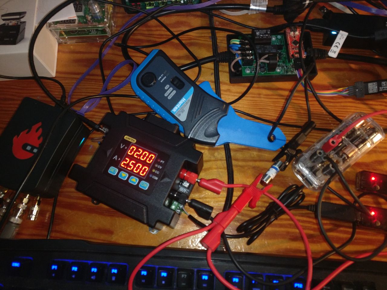
I’m using a DPM8608 power supply and a Mooshimeter. I have also connected a Red Pitaya oscilloscope with a Hantek CC-65 current probe because I will use that for later tests. The setup is a bit chaotic because there isn’t much free space on my desk. Sorry for that!
The Mooshimeter can do graphs. Very useful if the fuse blows while I’m not paying attention. This graph is from the Android app but it is also supported by Sigrok:

I have tested with 410 mA so slightly over the rated current (or so I thought, see below). The fuse survived for an hour before I got bored and moved on to the next test. So far, so good.
The Mooshimeter is connected to the same aligator clamps as the power supply so its voltage measurement will include the voltage drop of the clamps. If we want to calculate the resistance of the fuse, we will need the voltage directly at the fuse. The fuse has huge metal caps so I can use the Fluke to measure the voltage between those caps. The trick is that there isn’t any current going into the Fluke (well, almost none) so the contact resistance to the Fluke doesn’t influence the measurement. This is often called 4-wire or Kelvin measurement.
We get 0.171 V on the Mooshimeter and the Fluke agrees when connected to the alligator clamps. We get 0.144 V between the caps of the fuse. Thus, our estimate of the resistance would be 20% too high if we didn’t use 4-wire measurement. The resulting resistance is R = U/I = 0.144V/0.409A = 0.352 Ohms. I guess this is ok. Unfortunately, I don’t see any specs for resistance in the Bussmann datasheet and the description on AliExpress is very sparse on specifications - as usual. Thus, we have nothing to compare this to. I guess, the resistance could change over time (e.g. if the fuse is slightly damaged by the current or heats up significantly) but it is still the same after an hour.
Post scriptum: The fuse is for the 400 mA range of the multimeter but it is rated for 440 mA so I have tested it below its rated current.
Second check: Does it interrupt over-current and how fast?
Test setup: Set the power supply to 4 A (10 times the rated current of the fuse), set the oscilloscope to trigger on a rising edge of the current, enable the power supply.
The input is connected to a Hantek CC-65 current probe with 1mV/10mA. Thus, 50 mV/div is 0.5A/div. There is a small offset - I guess that I should calibrate the Red Pitaya again. The vertical cursors are at 0 mA and 400 mA, the trigger level is between them.
This is the result:
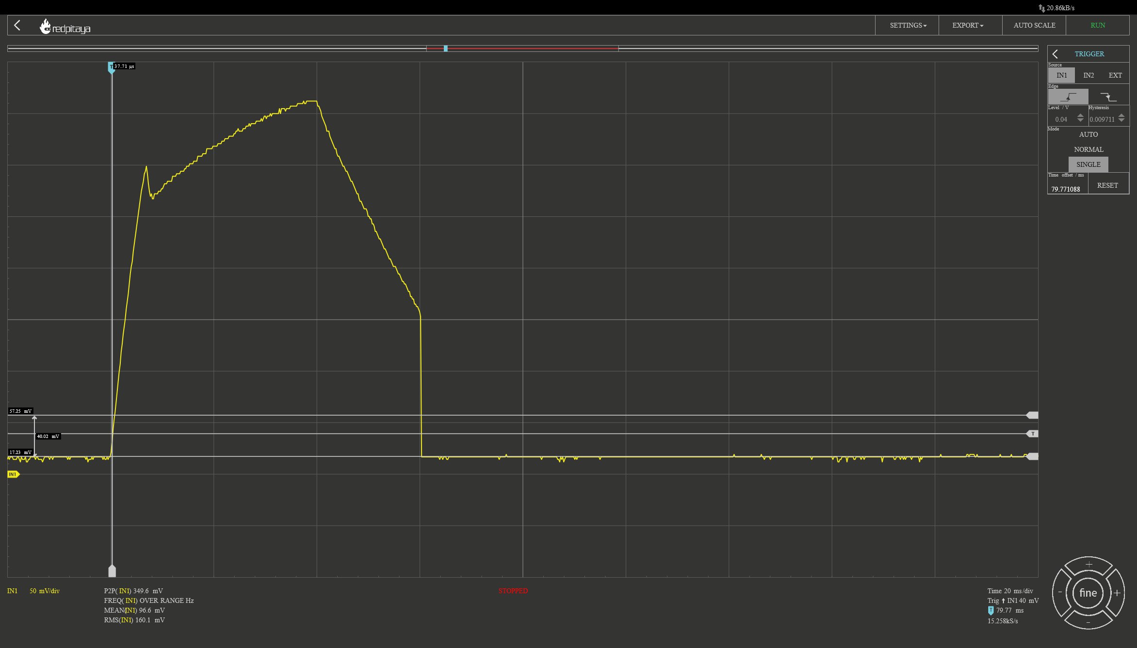
That’s weird: I had expected the current to rise until the fuse blows and then quickly fall to zero. That’s not what happens. Why?
The first part is quite simple: Many power supplies use a relay to enable/disable the output. The DPM8608 simply disables the voltage regulator. That way, we don’t have any contact bouncing but the current rises more slowly. That’s not ideal for our test but good for other uses of that power supply. Of course, I could plug the banana connector instead if I prefer fast rise times with bouncing.
Let’s turn on the power supply into a short circuit without the fuse:
This also has a spike at the beginning and then rises more slowly. That seems to be the closed-loop control behavior of the power supply when enabled into a short. After 140 ms, we can see the behavior when the power supply is disabled. This looks like discharging a capacitor and I assume it is exactly that.
First part solved. What about the second part? Why does the current start to fall after 40 ms?
Some friends at the Hackerspace helped me with that. Here is what I hadn’t considered: The fuse blows by melting so the wire inside will become very hot. We usually ignore that resistance depends on temperature but we shouldn’t do that in this case. I had set the voltage limit to 5V because “that’s plenty”. Well, it isn’t! The current starts to fall at 40 ms because we run into the voltage limit before the fuse blows.
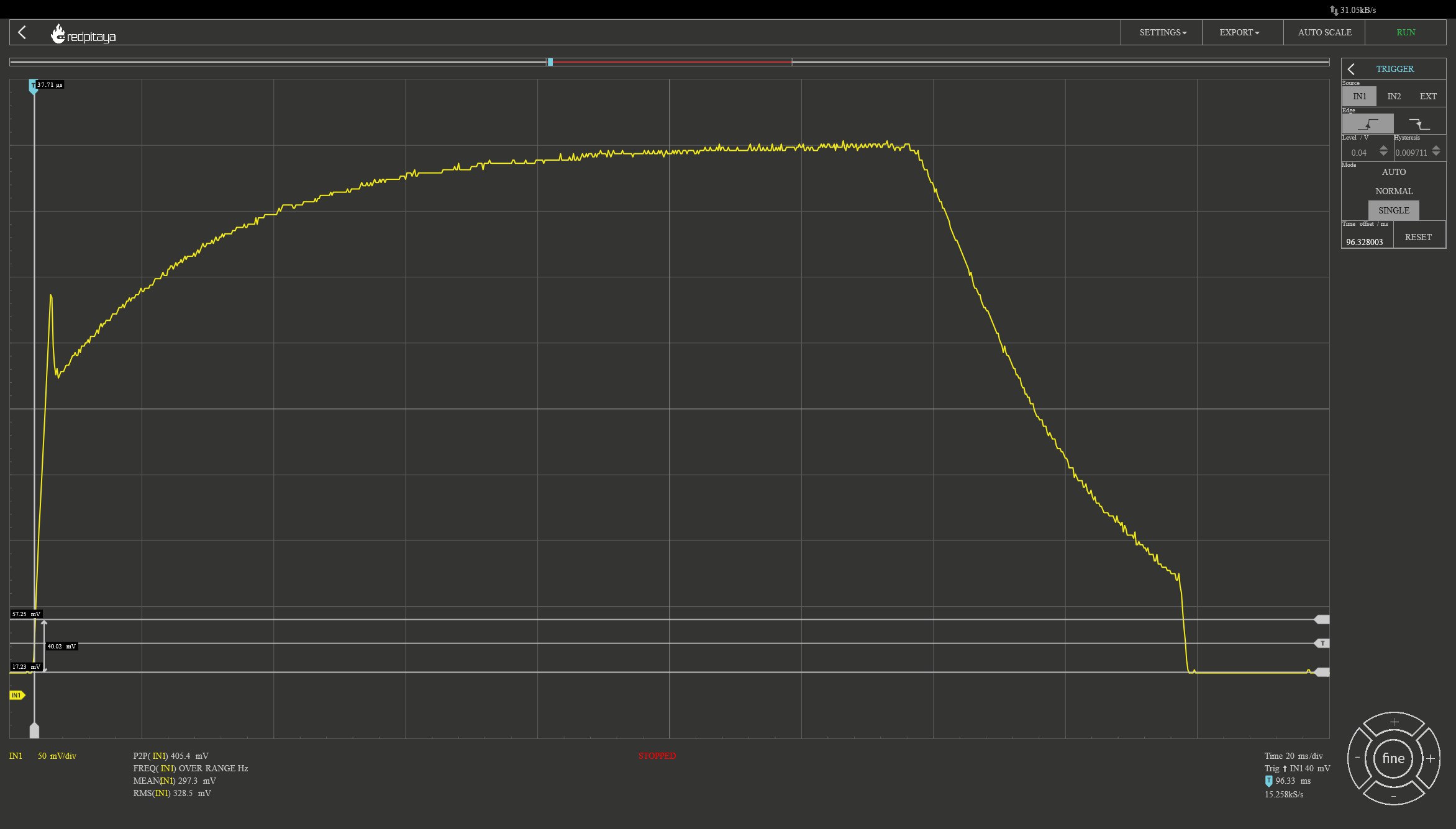
Here is my second try - this time with a voltage limit of 2V and we can see the voltage, as well:
We can see that the current starts to fall as soon as the voltage reaches 2V. The fuse did blow but only after the measurement interval so we don’t see this in the graph. D’oh.
Let’s assume that the wire is made of copper. Wikipedia says that copper has a melting point of 1084.62 °C and a temperature coefficient of alpha=3.93*10^−3 1/K. Thus, the resistance at the melting point will be: R_Tm = R_25*(1+alpha*(T_m - 25 °C) = 0.352 Ohm * (1+3.93e-3*(1084.62-25) = 1.82 Ohm. With that, we would have this current at the melting point: 5V / 1.82 Ohm = 2.75 A. The actual current is more like 1.5 A so I assume we have a material with a higher temperature coefficient and/ or melting point.
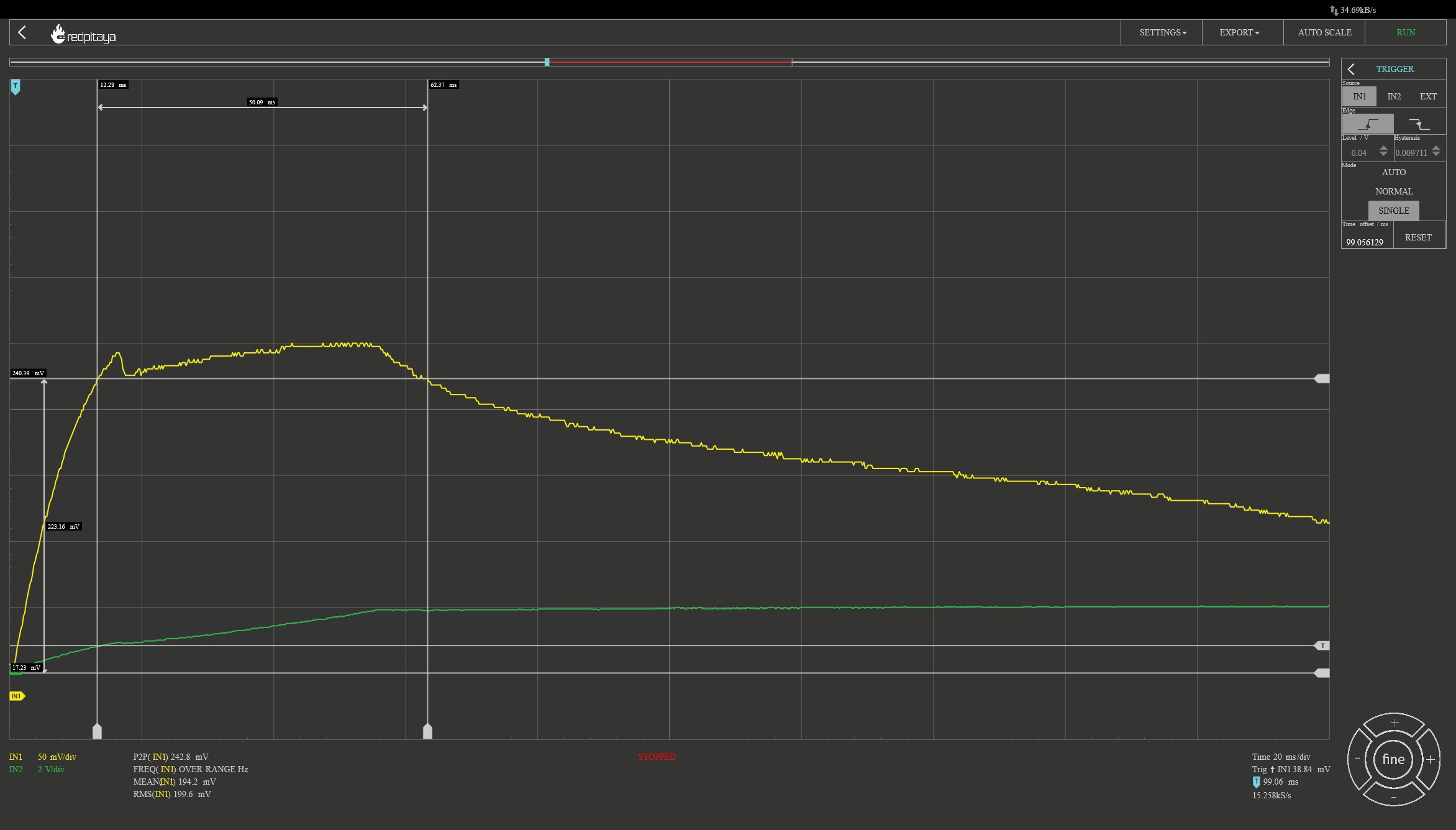
So, does the fuse pass or fail? Let’s have a look at the datasheet of the Bussmann fuse. Page 2 has a diagram with the time until the fuse blows for different currents. You can see that this can take minutes if the current is small enough. For the 4 A test, our fuse blew after 60 ms with an average curent of somewhere between 2.5 and 3 A. The diagram says, it should blow after 60 ms (0.06 sec) for a current that is slightly below 2 A. Thus, we are off by 25% to 50%. We had more current than that so our fuse is slower. We can also go in the other direction: 2.5A is below the chart so it should blow in less than 10 ms. It took 6 times as long! However, the curve is very steep so large differences in time are to be expected. EEVBlog has a video about this and they also find large variance in the times. They also explain how to read the chart in the datasheet.
For the second test, the current was above 2.4 A for 50 ms. This should blow the fuse according to the datasheet. This means that this fuse needs at least 20% more current than indicated by the datasheet. In addition, the current was above 1 A for most of the 200 ms. What does the datasheet say about that? Well, 1A is off the chart in the other direction. The fuse should survive this for quite a long time. However, it did blow and that’s ok because it was pre-heated by the 2.4 A. The curves in the datasheet only apply at room temperature.
With only two tries, there are very large error bars on our numbers and we don’t know how much variance there is for the original fuses (and whether the diagram shows the average or maximum time). Still, we can conclude that the “Bassmann” fuses blow at a higher current but probably not more than two times as much.
Conclusion
The fuses are different from the original ones: They need more current or time to blow. Thus, there will be a bit more stress on the multimeter. On the one hand, the difference is relatively small so the multimeter is still protected. On the other hand, do you really want to risk damaging a 300€ multimeter to save 3€ on fuses? Maybe, maybe not.
But there is more: I have only tested small currents and voltages. The fuses are rated for 1 kV and 10 kA. That’s a lot! There will be arcing and the fuse has to exstinguish that. Do I trust them to protect my multimeter and myself for CAT-III measurements? Not without a test! Unfortunately, I don’t see how I can do a safe and controlled test for that.
In addition, we want the fuse to have a low resistance because this will add to the burden voltage of the multimeter. My Fluke has a resistance of 1.4 Ohms for the 400 mA range (including the fuse) so the 0.352 Ohms of the fuse are the smaller part of that. Just a wild guess: The manufacturer might have focussed on low resistance at the cost of a higher trip current because that’s what customers can test at no cost.
To conclude, I think we can use the fuses for low voltage applications. If you do, please be careful and warn anyone who borrows the multimeter! Keep in mind that I’m not an expert on this (far from it!) so draw your own conclusions and whatever you decide is your responsibility not mine.
Update 1: What material is it?
We know that the wire inside the fuses melts at 5V / 1.5A = 3.33 Ohm. Can we use that to determine what material it is made of? Not quite because the resistance at the melting point depends on the melting temperature as well as the temperature coefficient (i.e. how much resistance changes with temperature). We need more information to solve for two unknowns.
The wire inside the fuse will be warmer than the outside of the fuse if we send some current through it. We don’t really know how much warmer it will be because that depends on how much energy is needed to heat up the material and how well the energy can dissipate to the outside of the fuse by thermal conduction. However, the fuse will get into a steady state if we keep power dissipation and ambient temperature constant: The wire will heat up until the energy that is conducted away is equal to the energy that we add. If we raise the ambient temperature, the temperature difference between wire and ambient should remain constant so the wire should heat up by the same amount as the ambient temperature.
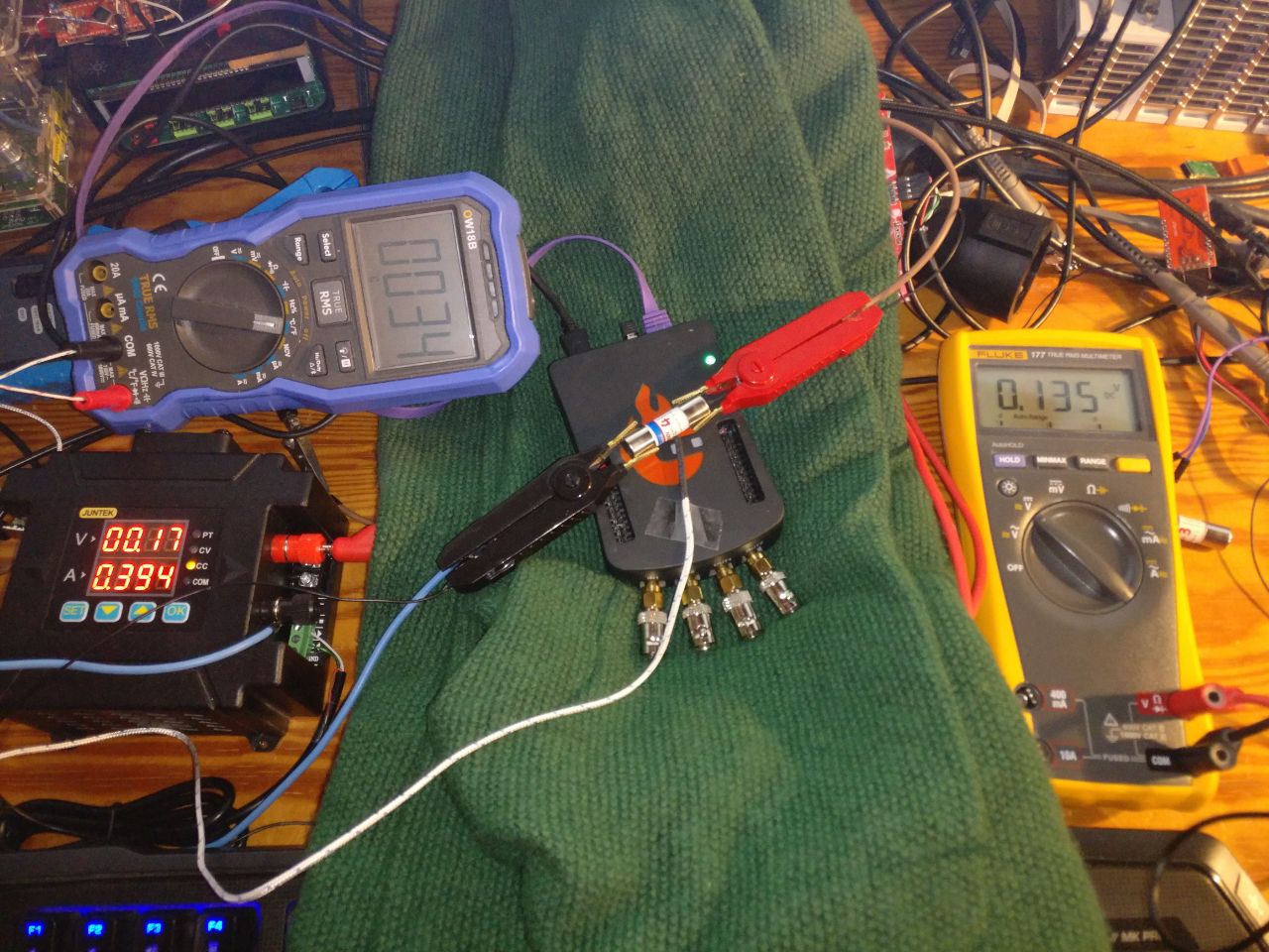
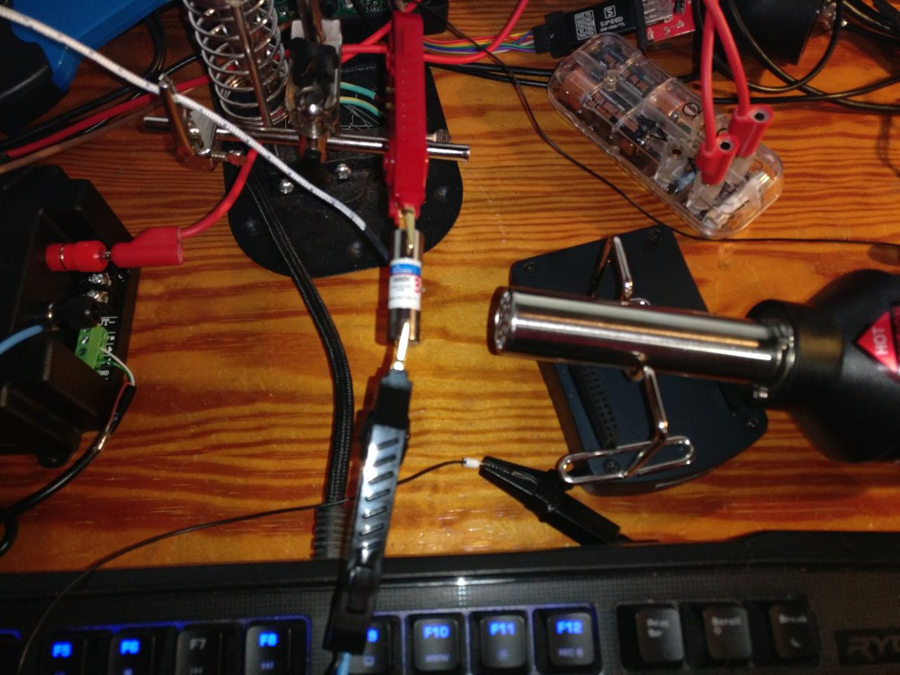
We need to accurately measure the resistance so we need 4-wire measurement. We can do it in the same way as yesterday:

This will work but there is a better way. Enter: Kelvin clamps.
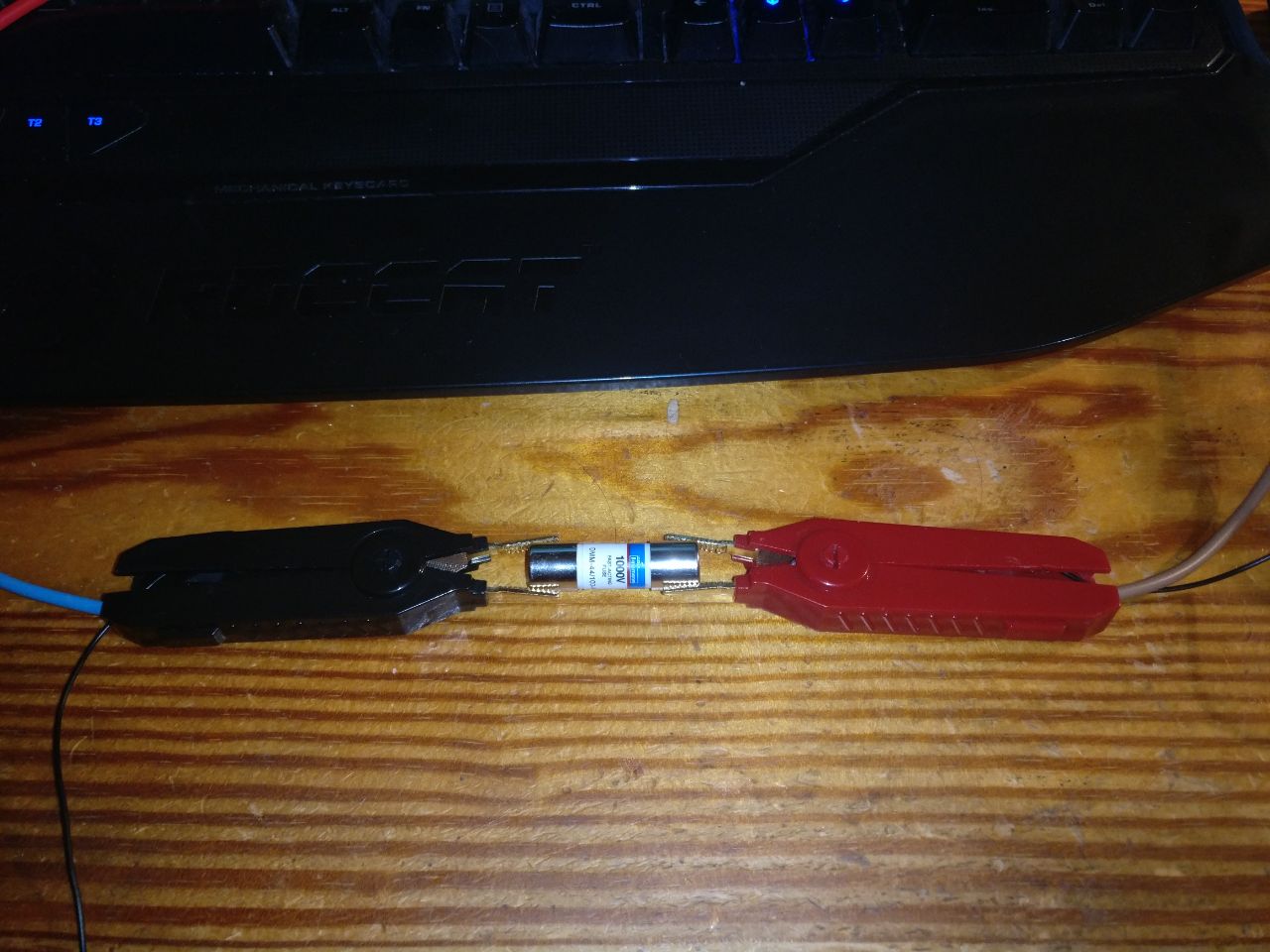
The jaws are isolated so we have two independent contacts for each clamp. Each clamp has one wire for the power supply and one for the voltmeter. I’m so glad that I have these around from another project.
Let’s do some measurements:
- We use the Red Pitaya as a heat source.
- The sweater will keep the heat inside and (hopefully) ensure a uniform temperature around the fuse.
- OW18B will measure the temperature.
- Mooshimeter will measure the current. It could measure voltage at the same time but we would have to connect both to the same common input, which we don’t want for 4-wire measurement.
- Fluke 177 will measure the voltage.
Here is what this looks like:
And here are the results:
# Columns:
# - Fuse Number
# - Temperature [C] (ambient, OW18B)
# - Current [A] (Mooshimeter)
# - Voltage [V] (Fluke 177)
data = """fuse_number   temperature current voltage
3   25  0.399   0.137
4   25  0.399   0.134
5   25  0.399   0.136
6   25  0.399   0.137
7   25  0.399   0.138
8   25  0.399   0.1375
9   25  0.399   0.131
3   25  0.100   0.031
4   25  0.100   0.031
5   25  0.100   0.031
6   26  0.100   0.033
7   26  0.100   0.032
8   26  0.100   0.031
9   26  0.100   0.0315
3   36  0.400   0.140
4   37  0.400   0.137
4   39  0.400   0.138
5   41  0.400   0.140
5   43  0.400   0.141
6   43  0.400   0.142
6   46  0.400   0.143
7   47  0.401   0.144
7   49  0.400   0.145
8   45  0.401   0.1445
8   47  0.401   0.145
9   50  0.400   0.140
9   52  0.401   0.141
"""

class NumMinMax(object):
    __slots__ = ("min", "max", "value")

    def __init__(self, value, min, max):
        self.min = min
        self.max = max
        self.value = value

    @staticmethod
    def with_error(value, error):
        return NumMinMax(value, value-error, value+error)

    def __repr__(self):
        return "NumMinMax(%f, min=%f, max=%f)" % (self.value, self.min, self.max)

    def __add__(self, b):
        if not isinstance(b, NumMinMax):
            b = NumMinMax(b, b, b)
        return NumMinMax(self.value+b.value, self.min+b.min, self.max+b.max)
    def __sub__(self, b):
        if not isinstance(b, NumMinMax):
            b = NumMinMax(b, b, b)
        return NumMinMax(self.value-b.value, self.min-b.max, self.max-b.min)
    def __mul__(self, b):
        if not isinstance(b, NumMinMax):
            b = NumMinMax(b, b, b)
        return NumMinMax(self.value*b.value, self.min*b.min, self.max*b.max)
    def __truediv__(self, b):
        if not isinstance(b, NumMinMax):
            b = NumMinMax(b, b, b)
        return NumMinMax(self.value/b.value, self.min/b.max, self.max/b.min)

temperature_error = 2
current_error = 0.001
voltage_error = 0.001


import csv, io
fuses = {}
with io.StringIO(data) as f:
    reader = csv.DictReader(f, dialect="excel-tab")
    for row in reader:
        fuse_number = int(row["fuse_number"])
        del row["fuse_number"]
        row["temperature"] = NumMinMax.with_error(float(row["temperature"]), temperature_error)
        row["current"] = NumMinMax.with_error(float(row["current"]), current_error)
        row["voltage"] = NumMinMax.with_error(float(row["voltage"]), voltage_error)
        if fuse_number not in fuses:
            fuses[fuse_number] = []
        fuses[fuse_number].append(row)
#display(fuses)

print("num:   %-7s  %-7s  %-7s  [1/K]" % ("avg", "min", "max"))
all_alphas = []
for num, measurements in fuses.items():
    m1 = None
    alphas = []
    for m2 in measurements:
        if m2["current"].value < 0.2:
            # ignore these for now because they have a different gradient from inside to outside
            continue
        if m1 is None:
            m1 = m2
            continue
        r1 = m1["voltage"]/m1["current"]
        r2 = m2["voltage"]/m2["current"]
        Tdiff = m2["temperature"] - m1["temperature"]
        # r2 = r1*(1+alpha*(T2-T1))
        # <=> alpha = (r2/r1 - 1)/(T2-T1)
        alpha = (r2/r1-1)/Tdiff
        alphas.append(alpha)
        all_alphas.append(alpha)
    alpha_avg = sum(alpha.value for alpha in alphas) / len(alphas)
    alpha_min = min(alpha.min for alpha in alphas)
    alpha_max = max(alpha.max for alpha in alphas)
    print("%d:     %7.4f, %7.4f, %7.4f" % (num, alpha_avg, alpha_min, alpha_max))

alpha_avg = sum(alpha.value for alpha in all_alphas) / len(all_alphas)
alpha_min = min(alpha.min for alpha in all_alphas)
alpha_max = max(alpha.max for alpha in all_alphas)
print("total: %7.4f, %7.4f, %7.4f" % (alpha_avg, alpha_min, alpha_max))

# Prefer the low-current measurement because it has less offset by internal heating.
R_25s = [m["voltage"]/m["current"] for num, measurements in fuses.items() for m in measurements if 24<=m["temperature"].value<=26 and m["current"].value < 0.2]
R_25 = sum(x.value for x in R_25s) / len(R_25s)
print("Resistance at 25 °C: %.4f" % R_25)

U_melt = 5
I_melt = 1.5
R_melt = U_melt / I_melt
# r2 = r1*(1+alpha*(T2-T1))
# <=> T2 = T1 + (r2/r1 - 1)/alpha
T_melt = (R_melt/R_25 - 1)/alpha_avg + 25
print("Rough estimation of melting temperature: %.1f °C" % T_melt)
T_melt_min = (R_melt/R_25 - 1)/alpha_max + 25
print("Rough estimation of melting temperature with alpha_max: %.1f °C" % T_melt_min)
num:   avg      min      max      [1/K]
3:      0.0018, -0.0000,  0.0056
4:      0.0018, -0.0000,  0.0050
5:      0.0018,  0.0004,  0.0039
6:      0.0019,  0.0006,  0.0039
7:      0.0019,  0.0007,  0.0034
8:      0.0023,  0.0011,  0.0041
9:      0.0026,  0.0016,  0.0042
total:  0.0020, -0.0000,  0.0056
Resistance at 25 °C: 0.3150
Rough estimation of melting temperature: 4758.2 °C
Rough estimation of melting temperature with alpha_max: 1729.0 °C
A melting point of almost 5000 °C. That can’t be right!
Let’s try something else: More temperature but less steady state:
The temperature will rise and fall very quickly with that setup so we don’t really have a steady state. My plan was to keep it at a constant temperature for some time but the hot air gun has significant variations in temperature so that won’t work. I heat it up and then take measurements while cooling down. That way, the multimeter will get an accurate reading of the case temperature, at least. The measurements are all over the place, though:
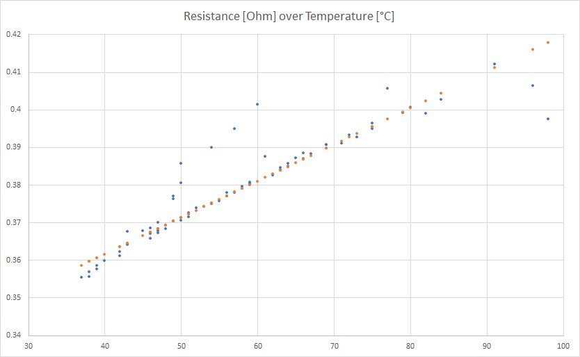
The blue dots are my measurements, the orange dots are for 0.347 Ohms at 25 °C and a thermal coefficient of 0.0028 1/K. This is not too far from my previous values but the melting point would be at 3100 °C. Still to high!
I know one problem with my measurements: I have to keep power dissipation constant but I do keep the current constant. Power dissipation will rise with resistance, which will increase internal temperature, which will increase the resistance. Thus, we will estimate an alpha that is too high but I think our alpha is actually too low.
I’m giving up for now. Those measurements cannot be right, I think. Do you have any ideas?
We can try something else: Wikipedia says that the wire is usually made of copper or silver.
R_25 = 0.310       # [Ohm], use measurement with low current for less inside heating
alpha_cu = 0.00393 # [1/K]
alpha_ag = 0.0038  # [1/K]
Tmelt_cu = 1085    # [°C]
Tmelt_ag =  962    # [°C]
Rmelt_cu = R_25 * (1 + alpha_cu*(Tmelt_cu - 25))
display(Rmelt_cu)  # -> 1.60 Ohm
Rmelt_ag = R_25 * (1 + alpha_ag*(Tmelt_ag - 25))
display(Rmelt_ag)  # -> 1.41 Ohm
Both of them don’t match the 3.33 Ohm that we have calculated earlier. Maybe my estimation of the resistance at the melting point isn’t right?
To be continued… as soon as I have more ideas for what I can try.
Future work
I still have seven fuses left. I don’t want to destroy them for no good reason and I might need some for my multimeter (not too many, I hope). Feel free to suggest additional tests.
- Calculate the energy and/ or
I^2*tfor my measurements. - Do a long term test at 440 mA and 1000 seconds at 1 A.
- Can we test the fuse at high currents? A friends has a capacitor bank. With that, we still cannot control the current but we can control the total energy. Is that enough for a useful test?
- Can we estimate the blowing current or energy in a non-destructive way, e.g. estimate wire diameter and heat dissipation at lower currents?
Seite 1 von 1